Topology
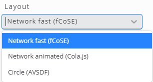
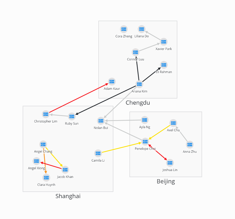
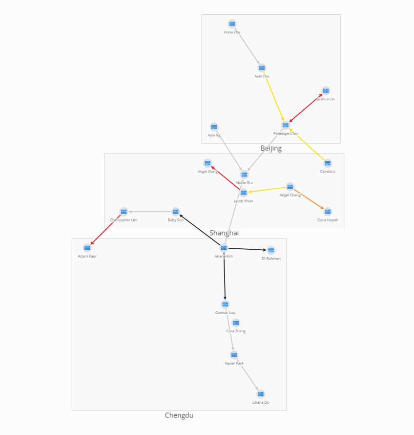
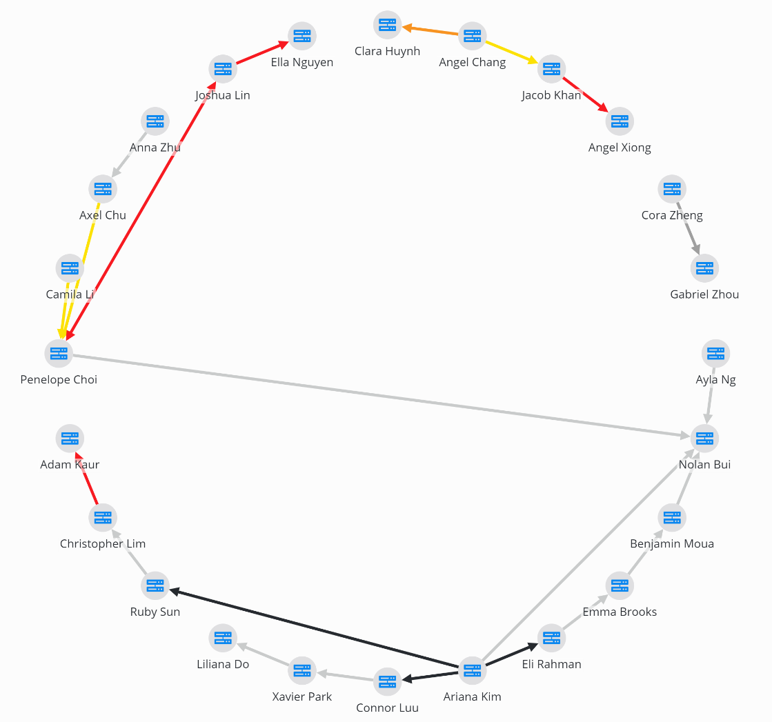
The topology widget is able to display topologies of networks and other objects. We provide several layout options:
 |  |  |
|---|
Editing Topology Widget
To configure a topology, select a Layout and specify either a Data Query or Data Source for Nodes and/or Edges.
To display Nodes without Edges, enable the Show nodes without edges option.
Next, configure the necessary fields for nodes and edges in the settings:
Configuration
Setting | Description |
|---|---|
Node ID column | Unique identifier |
Node Name column | Display name |
Node State column | Determines the color coding for nodes based on their state. Valid states include: OK (green), Warning (yellow), Minor (orange), Major (red), Maintenance (blue), No Data (grey), or Undefined (white) |
Node Icon column | To display a node icon use:
|
Node Group column | Nodes will be grouped based on this column. |
Edge ID column | Unique identifier |
Edge Name column | Display name |
Edge State column | Determines the color coding for edges based on their state. Valid states include: OK (green), Warning (yellow), Minor (orange), Major (red), Maintenance (blue), No Data (grey), or Undefined (white) |
Edge Source column | Specifies where the edge originates. The value in this column must correspond to an existing node ID. |
Edge Destination column | Specifies where the edge terminates. The value in this column must correspond to an existing node ID. |
SVG images used for node visualization automatically use the Accent 2 color settings defined in Settings / Theme.
Settings
Setting | Description |
|---|---|
Layout | Layout for placing items on the view:
|
Show nodes without edges | This setting determines whether to display nodes that do not have links. If disabled and no links are configured, no nodes will be displayed. |
Node click action | Define click action |
Edge click action | Define click action |
Parameters
Node parameters
Database column x of a node configuration can be accessed using the following notation:
${columns.x}
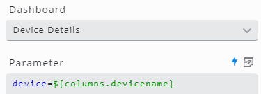
Example: The following Action on node click configuration opens the dashboard Device Details with URL parameter device set to the value of column devicename:
Edge parameters
Parameters like source or destination of links between nodes can have multiple values (e.g. in a connection between two devices, both can act as source and destination). Therefore they come in the form of arrays instead of single values (e.g. <value 1>,<value 2>). Although they are accessed the same way as single value parameters, they must be treated differently when used.
Example: Filter devices using edge configuration parameters:
device=IN(${columns.devicename})